User interface and operation
Each entrance is symmetric, and thus we can generate the left half and mirror it to the right. While starting from the center of the central entrance, we can hierarchically connect all components as a component graph, whose nodes are component icons, and edges are topological connections among components. As shown in following figure, we decompose and analyze existing Pailous to determine a set of structural components. At the same time, we collect and model corresponding 3D models for various structural components. While studying their semantic rules [Wan92], a parental component in the graph has a fixed set of plausible connecting components. For example, a pillar can allow the connection from a lintel but not from an inscribed board. We express all connection relationship as a relation matrix detailed in the following paragraph. Similarly, while starting from the cap, Toukungs are branch-like using repeated interconnection rules. Both structures are suitable for parametric L-system representations. In order to procedurally construct Toukungs in different levels and various Pailous, we derive different sets of L-system representations detailed in L-system.
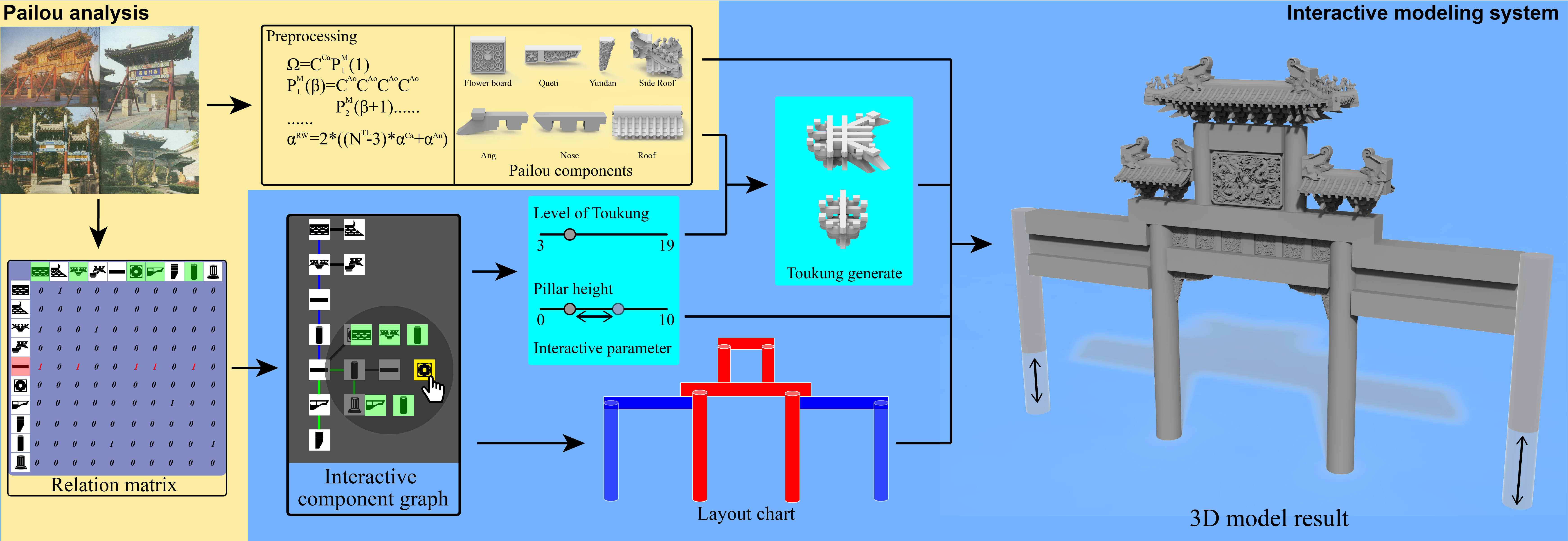
Fig. Preprocessing analyzes structural and topological rules to determine a set of structural components along with their 3D models, create a relation matrix of componential interconnection relationship, and derive L-system grammars for Pailous and Toukungs. During the run time, a user can interactively and incrementally add plausible component icons into a component graph based on the relation matrix and adjust component-based parameters while our system can immediately interpret the graph along with parameters to the corresponding Toukungs and Pailous.
In order to intuitively and simply create a Pailou in a few minutes for novices, we design an icon-based framework to interactively construct the component graph as shown in the following figures. Users start from a basic entrance of a lintel with two pillars. They can interactively identify an existing component as the active, and our system shows all legitimate components based on the corresponding row in the relation matrix. They can incrementally select the desired components, such as flower boards, by clicking the icon to add them into the component graph with default parameters. Additionally, users can also manipulate component-based parameters, such as the number of levels for a Toukung, to finely adjust their appearance. Currently, while changing happens, our system runs collision detection to avoid penetration among components. Furthermore, users can drag icons to have a better layout for examination. At the same time, our system analyzes the graph to create its layout chart and form L-system strings. Finally, it interprets the strings to create the corresponding 3D Pailou and Toukungs with the provided 3D components for immediate feedback.
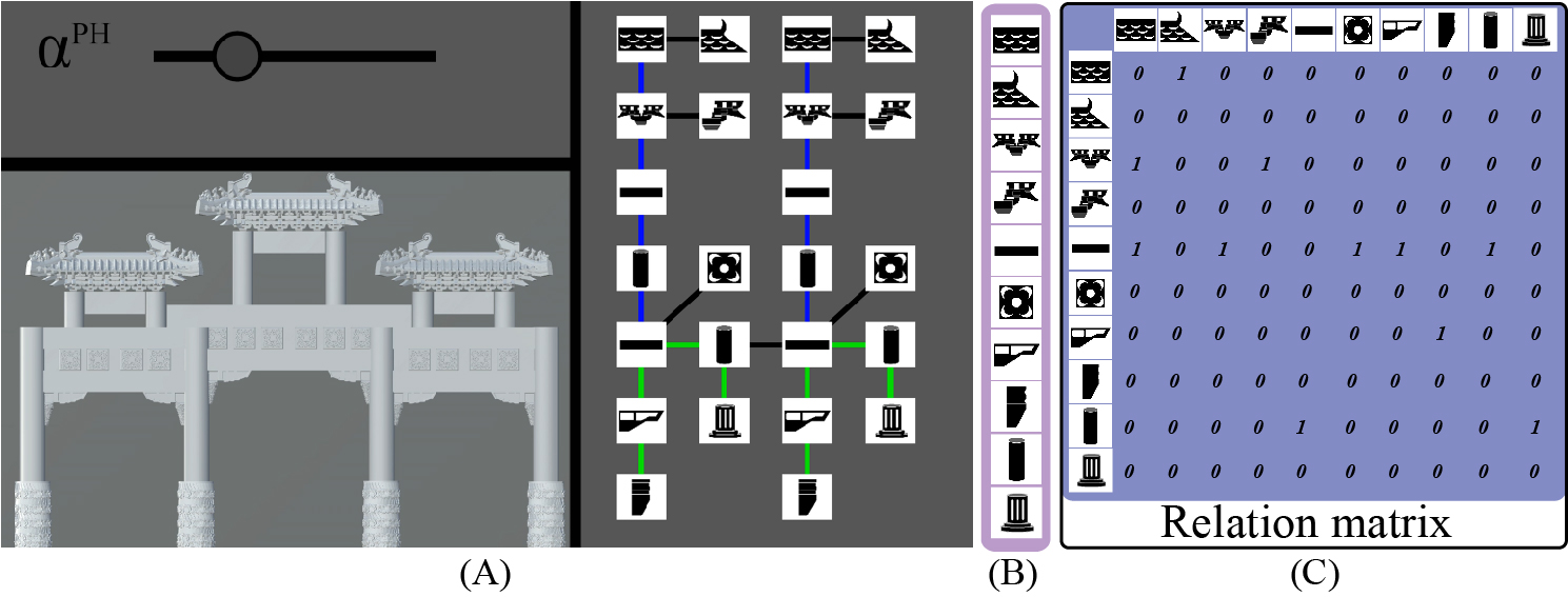
Fig. Our iconized interface mainly consists of two elements: a graph (A) to describe the topological relationship among components and components icons (B) along with the relation matrix (C). From top to bottom for the icon list are the clipped type of roofs, the eaves type of roofs, the middle Toukung, the side Toukung, the Lintel, the cylindrial pillar, the rectangular pillar, the Queti, the flower board, and the Yundan.

Fig. This shows an exemplar construction procedural. A user can start from a basic Pailou (a) and set the pillar as active component (marked in red) and the flower boards (marked in yellow) while our system show all legitimate components including Toukungs, flower boards, and Quetis (marked in green) (b). The process can repeat until we have the final result (d)(e). At the same time, the user also changes the level of Toukungs from 3 to 7 (f).
Generally, architects the lateral structures into three parts: main, repeating, and side where the main constructs the central entrance, the repeating constructs multiple middle entrances, and the side constructs the outmost entrance as shown in the following figure. Although the main entrance may have different structures, the lateral growth usually has the same layouts. Therefore, we provide a grouping mechanic to group an existing entrance set as a pre-built component graph and duplicate them to reduce the labor to append them forward and laterally
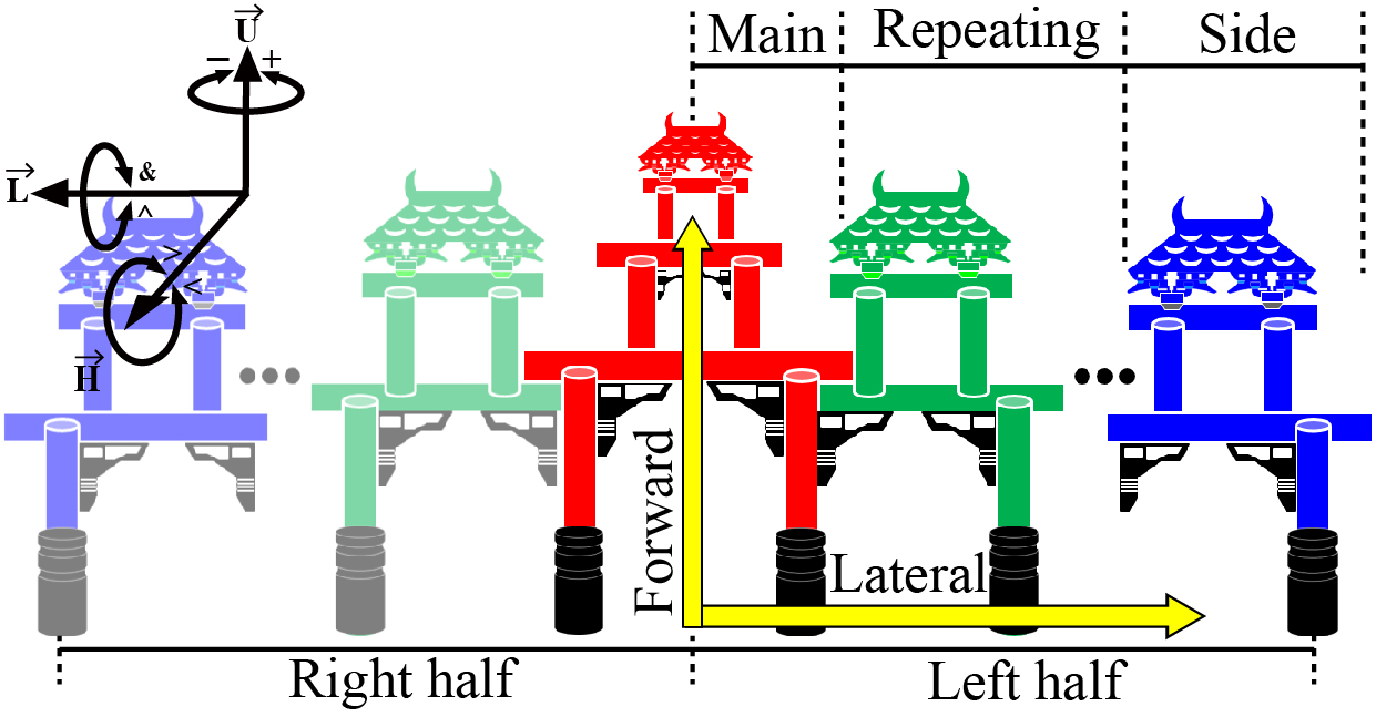
Fig This shows that Pailou are symmetric, and its topological layout can generally divide into the upward and lateral directions where the upward increases its height by adding entrances on the top and the lateral increases its width by adding entrances next to the current one.
Relation matrix
As shown in the following figure, this work uses a relation matrix to represent the legitimate linking relation between all possible pairs of components where a relation matrix is a N^C×N^C matrix. Originally, there are 8 structural components. However, roofs may optionally have eave corners, and thus, we have two different roof types: clipped and eaves roofs. Correspondingly, there are two different Toukung types: middle and side Toukungs. Therefore, our current implementation has 10 components. Each row is a structural component identified with its corresponding icon. While the boolean value at a column of the row indicates whether the column component can legitimately connect to itself. For example, 1 at the (5,3)-th element means that Toukungs can legitimately link to a lintel.
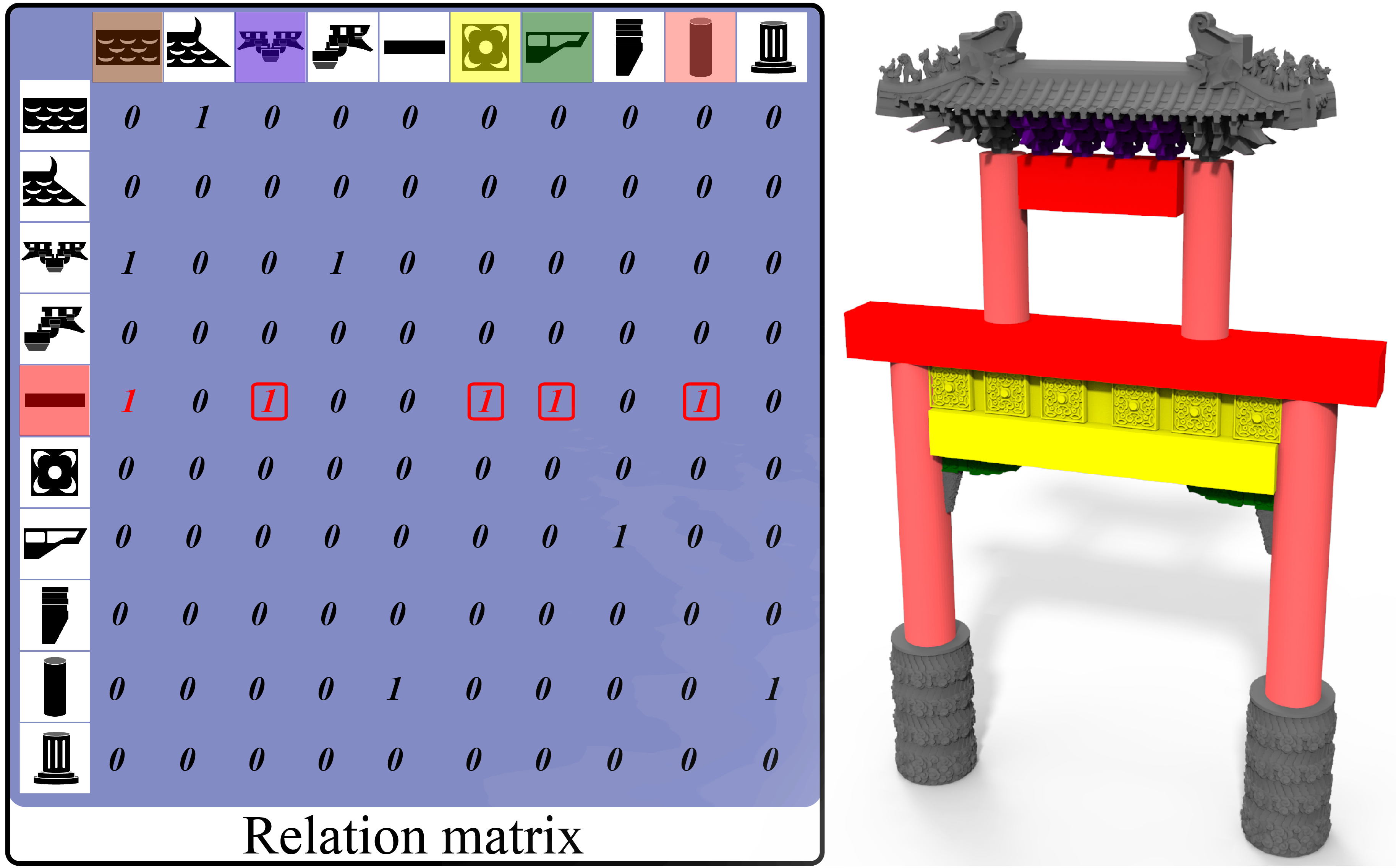
Fig. This shows an exemplar use of the relation matrix while the active component marked in red is the lintel listed in the 5-th row. All components plausibly connected to the lintel have their corresponding column of a value as 1 while Toukungs marked in blue, flower boards marked in green, pillars marked in purple, and Quetis marked in yellow are those actually selected in the right example.